OTF Studio demonstration and tutorial YouTube videos:
Getting Started: how to open OTF Studio project
Data management is an important part of any software. OTF Studio projects use the *.otfproj file extension. Each project file stores all related data - designs, targets, layer materials, substrates, illuminants, monitoring runsheets, settings, layouts and more - together in a single self-contained file. OTF Studio projects can be worked with in the standard way: new projects can be created, existing ones opened and closed, and Save or Save As used. To delete a project, the corresponding *.otfproj file simply needs to be removed from its folder. Projects can be stored in any location. This video walks through the first steps of getting started with OTF Studio, showing how to create a new project, open an existing one, or open an OTF Studio example. Whether for a beginner or a returning user, this guide will help get up and running quickly.
Ribbon Interface Overview
This video walks through the OTF Studio ribbon interface. The ribbons provide access to the main operations and tools of OTF Studio.
Docking Panels Explained
OTF Studio uses a canvas-based interface with ribbon toolbars. Work takes place on a fixed layout - similar to a sheet of paper - where plots, panels, databases, and diagrams can be positioned. The docking interface of OTF Studio allows panels, plots, and diagrams to be moved and repositioned anywhere on the layout. The ribbons provide access to the main operations and tools of OTF Studio, while the docking panels help organize the workspace layout.
Plots in OTF Studio
📈 The features used every day when evaluating and designing multilayer coatings include plots. OTF Studio provides a wide range of plot types: spectral and angular plots, electric field and phase distributions, arbitrary 2D plots, fitting plots, and plots in monitoring mode. This video focuses on the plot types most commonly used in practice.
Plots: Y‑Axis - Scales, Units, and Second Axis
📈 OTF Studio's secondary Y-axis feature allows compact, informative plots to be built by combining several characteristics in a single view - among other examples, this video demonstrates how to plot spectral characteristics in % or absolute units together with optical density (OD) in one plot.
Color Evaluation Features
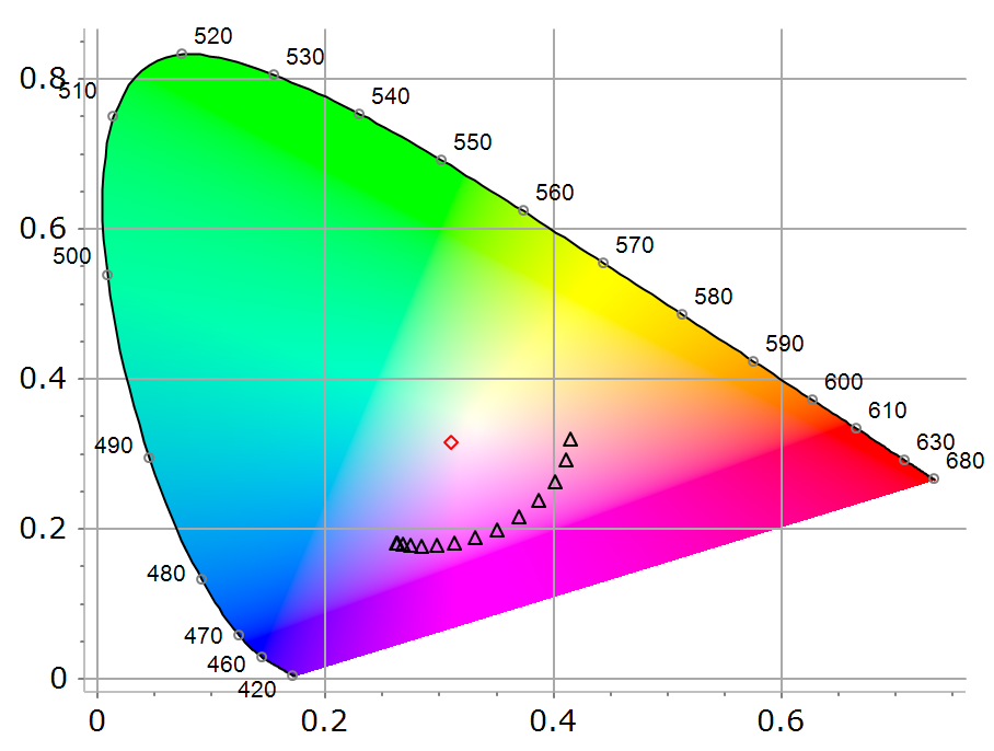
Optical coatings with specified color properties are used in virtual reality, architectural glass, automotive glazing, lenses, cameras, displays, and many other applications. OTF Studio provides a wide range of color-related features: color design, color evaluation of designs, color evaluation of produced coatings based on measurement data, color comparison, color-difference calculation, and calculation of color-related parameters (Color Rendering Index (CRI), Duv, complementary and dominant wavelengths, purity, yellowness index, and color-correlated temperature (CCT)). This video focuses on color evaluation features in OTF Studio. It demonstrates color diagrams in various color spaces, multiple color evaluation panels, and dynamic color evaluation when the interactive analysis tool (Variator) is active.
Designing an Angle-Dependent Color Coating
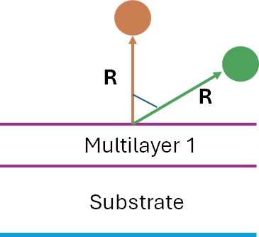
This video demonstrates the design of a coating whose reflected color visibly shifts hue as the viewing angle changes - from a warm orange at normal incidence to a bright green at 60°. Another coating is designed to shift hue in the opposite direction: from bright green at normal incidence to warm orange at 60°. Layer materials: TiO₂, SiO₂. Finally, the color angular trajectories of the two designs are compared.
Designing a Coating with Illuminant Dependent Color
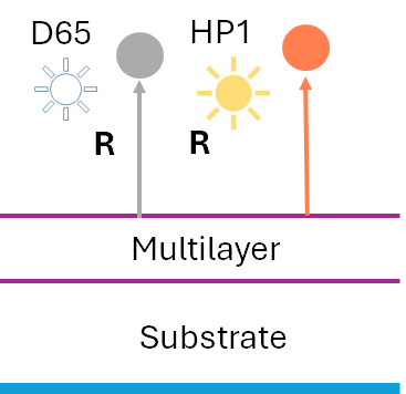
This video demonstrates the design of a coating whose reflected color depends strongly on the illuminant - neutral gray under D65, shifting to a warm orange-pink under HP1. This behavior is an example of illuminant metamerism, where a surface's perceived color changes with the spectral content of the light source rather than remaining fixed. Layer materials: TiO₂ and SiO₂. To achieve different color properties under the two illuminants, two different environments are configured, with synthesis performed in both simultaneously. Both colors are depicted on one color diagram at the same time using the Freeze feature of OTF Studio.
Designing a Coating with Front/Back-Dependent Reflectance Color
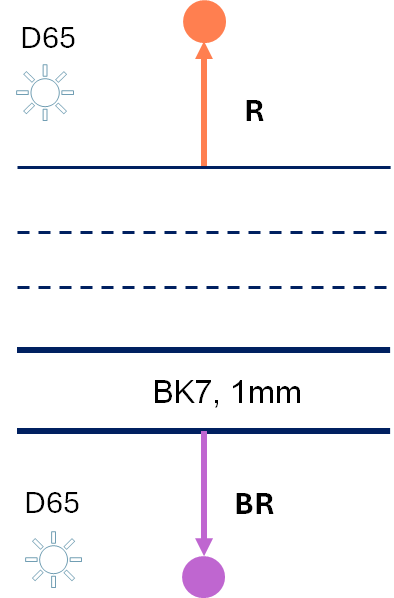
This video demonstrates the design of a coating that reflects different colors from its front and back sides: warm orange from the front, and pink-purple from the back, both under the D65 illuminant. Achieving different reflectance colors on the front and back sides requires an absorbing material in addition to the dielectrics. As the absorbing material, a 12 nm gold metal-island film is used; as dielectrics, TiO₂ and SiO₂ are used. The design must satisfy several technological requirements: the gold layer must be sandwiched between two SiO₂ layers, each with a thickness of at least 80 nm, and only one metal layer is allowed. Finally, Monte Carlo simulations in OTF Studio are used to demonstrate how they help investigate the color stability of the obtained design.
Designing an Omnidirectional AR Coating with Angle-Independent Reflectance Color
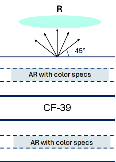
This video demonstrates the design of a double-sided ophthalmic AR coating with a stable green cosmetic tint across viewing angles. For this design task, two target functions are used: an antireflection target and a color target. To keep the cosmetic tint stable across an angular range of 0-45°, OTF Studio's Linked Colors tool is used. A single-side multilayer is designed first, then the double-sided element is composed using OTF Studio's Stack structure, and the colors of the resulting stack are refined. Finally, the angular color pattern of two elements is compared: a pure AR stack, and a stack optimized using both a spectral AR target and a color target.
Electric Field Distribution Plot
Electric-field evaluation shows how light behaves inside a coating and where the design is most sensitive - information that's essential whenever the internal field level directly affects performance, damage threshold, or sensing efficiency. Typical applications include laser-related multilayer designs and multilayer coatings used in sensors. This video demonstrates electric-field plots in OTF Studio along with estimations of laser damage threshold (LDT).
Dispersive mirror in mid-infrared range
This video turns to dispersive mirror design for the mid-infrared range. It demonstrates the design of a dispersive mirror operating over the one-octave spectral range 6-12 μm and compensating the group delay variation accumulated in 1 mm of ZnSe, with layer materials Ge and YbF₃. A good starting design is shown. As a target, the floating-constants feature of OTF Studio is used. The video also discusses how to design dispersive mirrors for large GD variations. Finally, the results are verified using the Pulse Analysis tool of OTF Studio.
Dispersive Mirror Design
This video demonstrates the design of a dispersive mirror operating in the spectral range 600–900 nm and providing group delay dispersion (GDD) of −40 fs², with layer materials Nb₂O₅ and SiO₂. A good starting design is shown. It illustrates how GDD ripples affect the pulse after interaction with the dispersive mirror. Three different approaches to target generation are considered. The results achieved via the group delay target with floating constants are demonstrated. Finally, the results are verified using the Pulse Analysis tool of OTF Studio.
Workspace Templates
OTF Studio allows the preferred layout - panel sizes, positions, fonts, and other visual settings - to be saved as Templates. With templates, the setup can be restored every time the application is opened, adapting the interface to individual workflow, screen size, and personal preferences.
Importing and Reverse Engineering 2D Data Sets in OTF Studio

In large-area optical coatings, such as architectural glass and mass-production runs, it is often essential to import and analyze measurements taken from various sample positions within a single reverse engineering workflow. OTF Studio provides fast and flexible tools for importing and processing batch measurements, i.e., spectral data recorded at different sample positions or for multiple quasi-identical samples. This video demonstrates how to import position-resolved measurement data into OTF Studio, perform optical characterization, and visualize the results using color-coded contour maps.
Import and processing of batch measurements

OTF Studio provides fast and flexible tools for importing batch measurements, i.e., spectral data recorded at different sample positions or for multiple quasi-identical samples. This video demonstrates how to import position-resolved measurement data into OTF Studio, perform optical characterization, and plot the results.
Stress Minimization in Multilayer Design
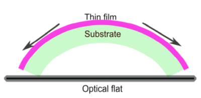
Large total thickness in mid-infrared optical coatings can lead to serious defects - such as buckling, cracking, and delamination. This video introduces the powerful Stress/Thickness target function in OTF Studio software. In this example, the concept is demonstrated using a broadband AR coating intended for operation in the mid-infrared spectral range. A standard AR spectral target over the broadband range 6-11 µm is combined with OTF Studio's Stress Minimization Target. Layer materials: Ge and YbF₃; substrate: ZnSe. The stress values of Ge and YbF₃ are set to −50 MPa and 140 MPa, respectively. The video walks through configuring the Stress Minimization Target feature in OTF Studio to minimize stress and reflectance simultaneously.
Coating Thickness Constraints: Total and Material-Specific
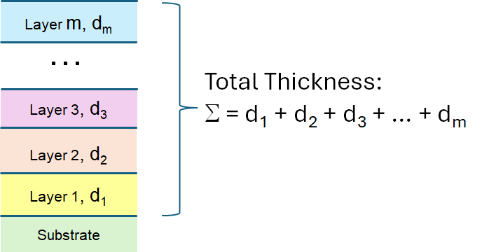
This video introduces the powerful Stress/Thickness target function in OTF Studio software. This video demonstrates how to control the overall thickness of a multilayer design, as well as set limits for individual materials, and walks through the process of configuring thickness targets and synthesizing multilayers that meet both spectral performance and thickness constraints simultaneously. It shows how to design a dichroic beamsplitter operating at 45°, with reflectance exceeding 98% in the range 590–640 nm and transmittance exceeding 98% in the range 670–710 nm. Layer materials: TiO₂ and SiO₂. Two versions of an additional requirement are considered: (1) the total physical thickness of the design may not exceed 3.8 µm, and (2) the total thickness of TiO₂ layers may not exceed 1 µm.
Stress Compensation through Back-Side Coating
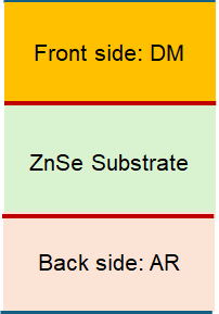
This video demonstrates how back-side design can be used to compensate for stress introduced by front-side design, using OTF Studio software. The example features a dispersive mirror optimized for the mid-infrared spectral range, paired with a compensating anti-reflection (AR) coating. The video walks through the process of exploiting OTF Studio's powerful Stress Target feature to engineer coatings with balanced stress profiles.
Reverse Engineering of a 10-layer Ge/YbF3 Beamsplitter operating at the Brewster angle of ZnSe substrate. Illustration of the Design Recipe feature.

Post-production optical characterization, or reverse engineering, of produced multilayers provides feedback to the deposition process. Reliable reverse engineering results enable adjustments to deposition parameters and, ultimately, improvements in production quality. This video demonstrates reverse engineering of a fabricated 10-layer beamsplitter using OTF Studio software. The beamsplitter operates in the near-infrared and mid-infrared spectral ranges. Layer materials: Ge and YbF₃; substrate: ZnSe. A model is applied that assumes systematic errors in the layer thicknesses. The video also demonstrates OTF Studio's practical Design Recipe feature, which can save the design obtained from the reverse engineering process while taking the estimated correction factors into account.
Characterization of Monolayers with OTF Studio: TiO2 Film
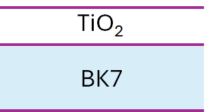
One of the key prerequisites to producing high-quality optical components is accurate knowledge of the optical constants of thin-film materials. The optical constants of layer materials can depend on the deposition technology and process parameters used. This video demonstrates the optical characterization of a TiO₂ monolayer using OTF Studio software. The film was produced by electron-beam evaporation; substrate temperature: 230°C; substrate: BK7. Two independent optical characterizations of the film are performed: one based on reflectance and transmittance data measured in the range 350-1100 nm, and another based on ellipsometric measurements. At the end, the refractive index wavelength dependencies obtained from R/T and ellipsometric data are compared.
Substrate Characterization using Semi-Analytical Method
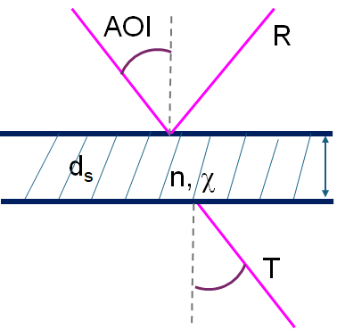
Substrate characterization means determining a bare (uncoated) substrate's optical constants - refractive index n(λ) and extinction coefficient k(λ) - from measured transmittance and/or reflectance spectra. Why it matters: any error in the assumed substrate optical constants can affect evaluation, design, monitoring, and post-production characterization results, since a designed or deposited multilayer's performance is always substrate-plus-coating together. Therefore, precise knowledge of substrate optical properties is essential for the theoretical design and monitoring of optical coatings, as well as for layer characterization and reverse engineering of produced multilayers. For broadband design and production, it is important to know accurate substrate data across the entire spectral range. This video demonstrates a reliable semi-analytical method for estimating optical constants of substrates using OTF Studio software, illustrated for the characterization of S-LAH66 and ZnSe substrates.
Designing a multi-band filter
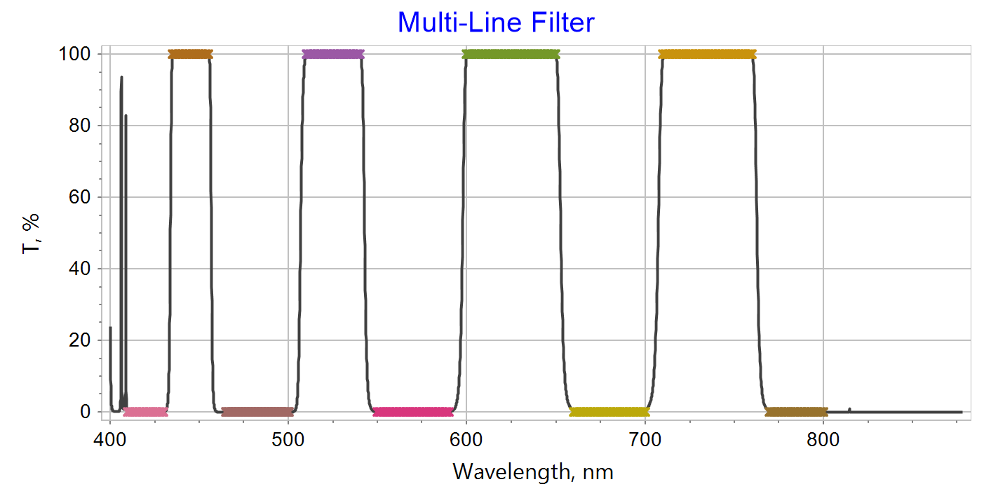
A multi-band filter is a multilayer coating whose reflectance and transmittance exhibit several distinct passbands and stopbands - spectral ranges where light is transmitted or blocked - separated by regions of opposite behavior. These filters are characterized by high optical density in the blocking ranges, high transmittance in the passbands, and steep transition zones between them. This video demonstrates how to design a challenging multi-band optical filter using OTF Studio thin-film software. The filter features five narrow low-transmittance zones and four narrow high-transmittance zones. TiO₂ and SiO₂ are used as the layer materials for this demonstration.
Designing an antireflection coating in the visible spectral range
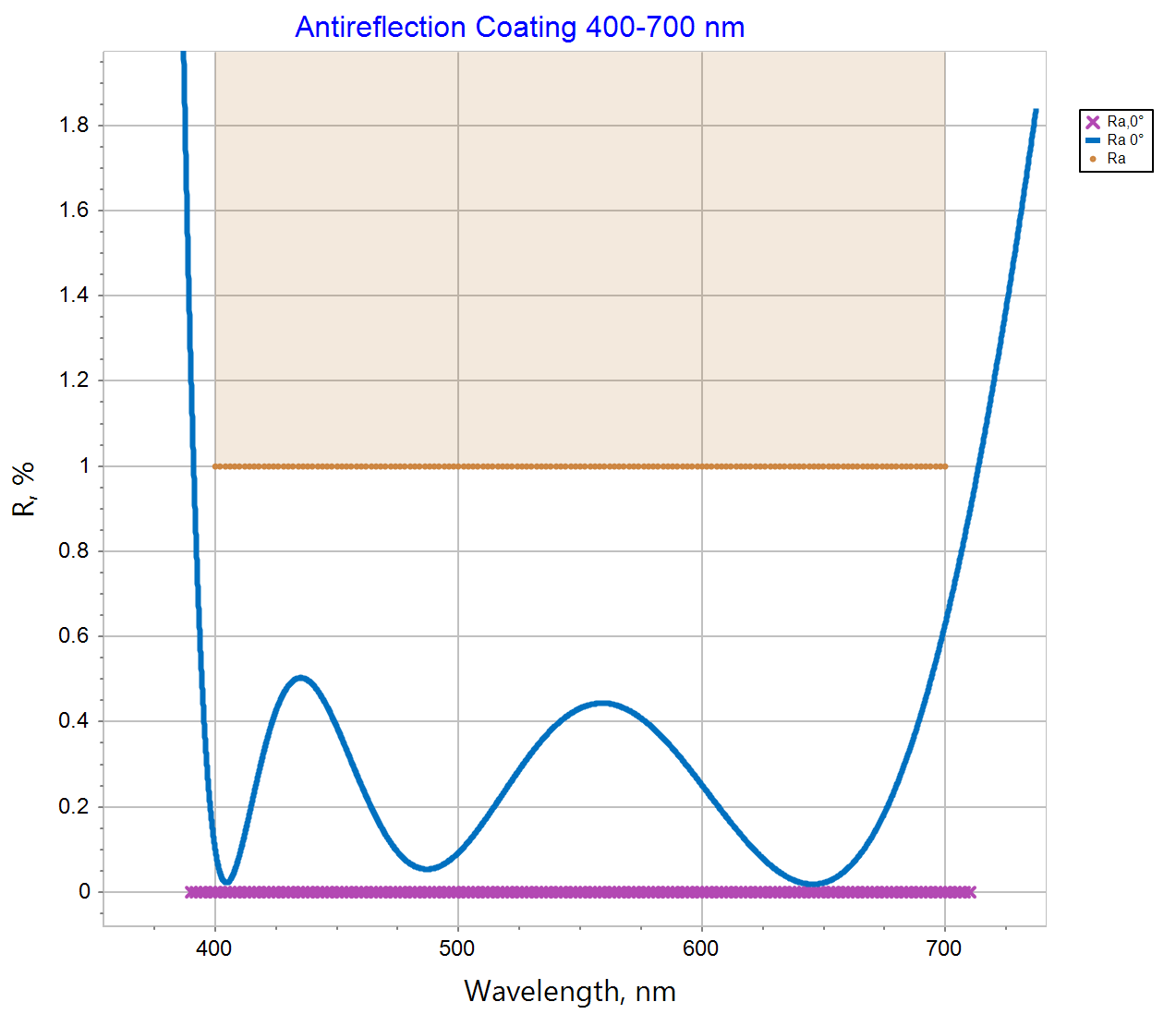
Anti-reflection (AR) coatings minimize surface reflection at a target wavelength or across a spectral range. A simple single-layer AR coating works well only over a narrow spectral range; multilayer designs extend the low-reflectance region. This video demonstrates how to design an effective anti-reflection coating for the visible spectral range using OTF Studio Thin Film Software. A classic combination of TiO₂ and SiO₂ is used as layer materials to minimize reflection. The video walks through the design process, shares key insights, and showcases practical results.
Designing a dual-band antireflection coating (VIS-NIR)
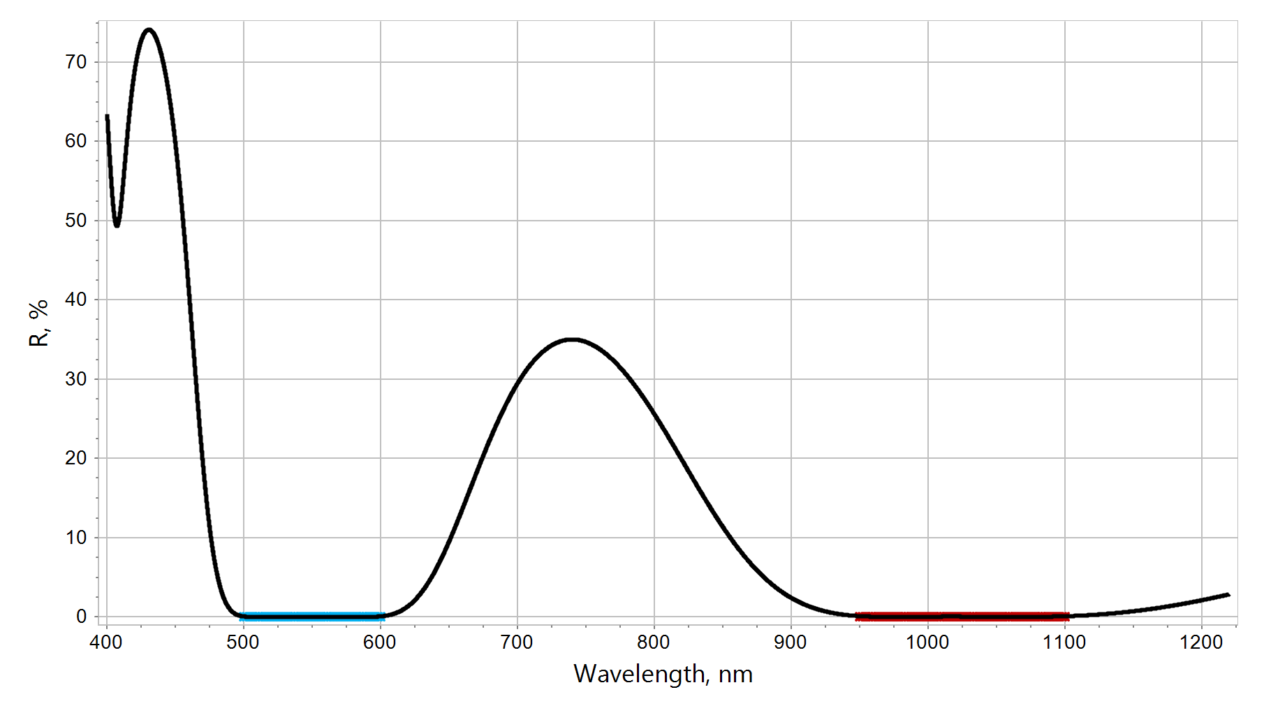
Dual-band AR coatings suppress reflection simultaneously at two separate, spectrally distinct wavelength ranges. They are useful wherever a system operates at two distinct spectral ranges at once - for example, in laser systems using a fundamental wavelength and its second harmonic (e.g., 1064 nm / 532 nm or 1030 nm / 515 nm), dual-wavelength sensors or imaging systems (e.g., visible + NIR), combined pump/signal optics in fiber laser or amplifier systems, or multi-spectral optical instruments needing transmission windows at two separated bands. This video demonstrates a quick and efficient design process for a dual-band anti-reflection coating operating in the 500-600 nm and 950-1100 nm wavelength ranges, using OTF Studio thin film software.
Designing an omnidirectional anti-reflection coating in the visible range and in the angular range 0-60°.
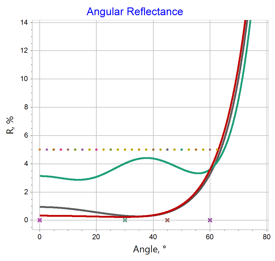
Broadband omnidirectional AR coatings provide low reflectance not just at normal incidence, but across a wide range of angles. They're used in numerous applications, including solar cells, smart windows and displays, wide-field-of-view cameras and sensors, LED encapsulation and light-extraction surfaces, display covers and touch panels, and automotive and architectural lighting optics - any window or lens meant to perform consistently regardless of viewing or illumination angle. This video demonstrates how to design an omnidirectional anti-reflection coating that operates in the visible spectral range and maintains low reflectance across an angular range of 0° to 60°, using OTF Studio software.
Designing a Mid-Infrared Anti-Reflection Coating with OTF Studio (7-12 um)
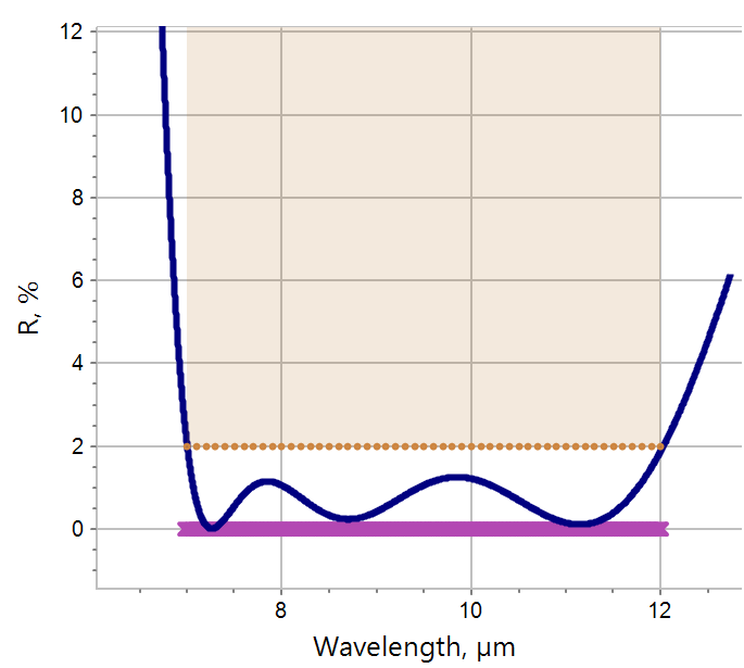
Mid-infrared (MIR, roughly 3–15 μm) multilayer designs differ from visible/NIR coatings in several important ways. Because standard glass substrates and visible-range oxides (SiO₂, TiO₂, Al₂O₃, Ta₂O₅) absorb strongly in the MIR, both the substrate and the layer material combinations change. Typical MIR substrates include ZnSe, Ge, Si, ZnS, CaF₂, and various crystals; common MIR thin-film materials are Ge, ZnS, YbF₃, MgF₂, and Si. Layer thicknesses in the MIR are typically about 10 times larger than in the visible range, which can lead to stress issues, and capping and adhesion-promoting layers are often added to address absorption and adhesion challenges. This video demonstrates how to design a mid-infrared double-sided anti-reflection optical element using OTF Studio thin-film software. Operating spectral range: 7-12 µm. Layer materials: ZnS and YbF₃. Substrate: ZnSe. Reflectance of the double-sided element must stay below 2%. The design includes a ZnS cap layer. Additional practical constraint: each YbF₃ layer must be thinner than 1.2 μm.
Designing Triple-Band Anti-Reflection Multilayers
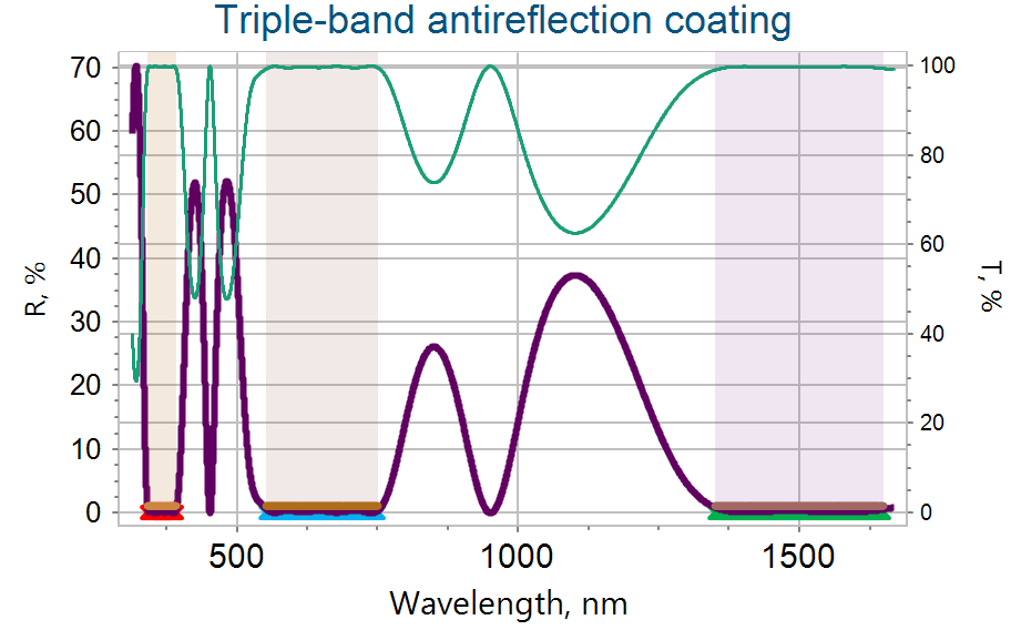
Triple-band AR coatings are specialized multilayers designed to minimize reflection at three distinct spectral bands simultaneously. This video demonstrates the design of a triple-band anti-reflection multilayer using OTF Studio thin-film software. The coating provides low reflectance in three spectral ranges: 340-390 nm (around 360 nm), 550-750 nm (around 633 nm), and 1350-1650 nm (around 1550 nm) - chosen to cover three widely used laser wavelengths: near-UV diode lasers, the HeNe laser line (632.8 nm), and the 1550 nm telecom band.
Designing Single and Dual-Wavelength AR coatings
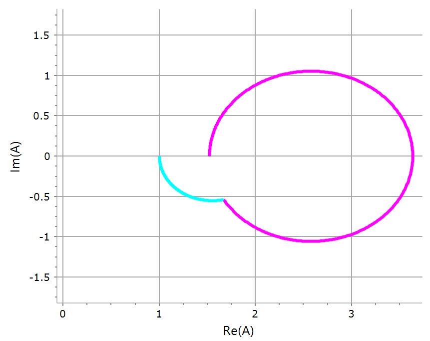
This video demonstrates how to design simple anti-reflection coatings for one or two laser wavelengths using OTF Studio thin-film software. It shows how to design a "V" coating at 532 nm and a "W" coating at two laser wavelengths, 532 nm and 1064 nm. The video also showcases the admittance diagram, as well as 2D and 3D plots within the software.
Bandpass optical element with a dynamically adjustable high-transmittance range.
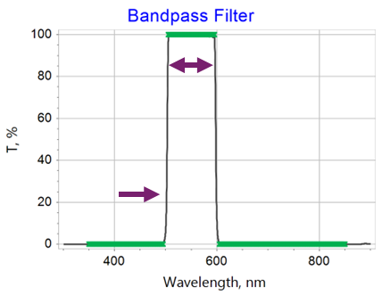
A bandpass filter is a multilayer coating that transmits light within a defined wavelength range (the passband) while reflecting or blocking light outside it, on both the short- and long-wavelength sides. Bandpass filters can be designed directly, using bandpass filter targets that specify high- and low-transmission zones. But there is an alternative approach: a bandpass filter can be composed as a double-sided optical element, with a shortpass filter on one side and a longpass filter on the other. Longpass filters are optical multilayers that reflect short wavelengths and transmit long wavelengths. Shortpass filters are optical multilayers that reflect long wavelengths and transmit short wavelengths. By varying only one parameter - the control wavelength - of one of the filters, the high-transmittance zone changes dynamically. Such double-sided elements may exhibit lower stress and scattering than an equivalent single-side bandpass design. This video demonstrates how to design a bandpass optical element with a dynamically adjustable high-transmittance zone using OTF Studio software. A longpass and a shortpass filter are designed first, combined into one double-sided optical element, and then the high-transmittance zone adjustment is demonstrated. Good starting designs for both filter types (long and shortpass filters) are also suggested.
Broadband High Reflector
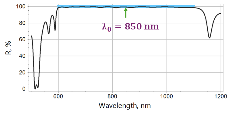
High-reflective (HR) optical coatings maximize the reflectance of an optical surface within a spectral range of interest; spectral behavior outside that specified HR region is typically not of interest. The most important characteristics of HR coatings are the width of the HR zone, peak reflectance R₀, and average reflectance over the HR range. Dielectric HR multilayers are a good alternative to metal mirrors, though their operating spectral range is much narrower. OTF Studio can solve HR design tasks quickly and effectively. This video shows a very simple way to design a high reflector for the broadband spectral range of 600-1100 nm. Reflectance must be higher than 98.5% across the entire HR range. Layer materials are TiO₂ and SiO₂. A good starting design - a chirped mirror - is also shown.
High Reflector with Optimized Electric Field Distribution
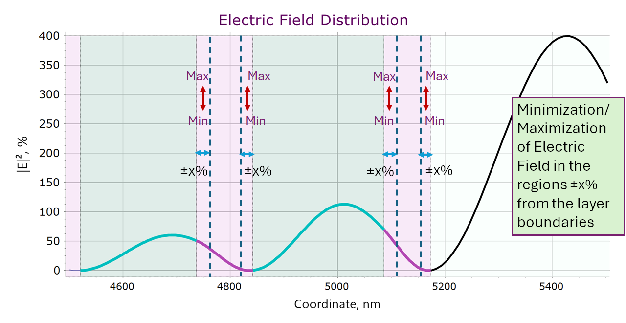
Electric-field optimization in optical multilayers is a key capability for a range of applications. In high-power laser systems, high peak electric-field intensity can lead to damage in multilayer coatings; by tailoring the design to suppress the field near interfaces in high-index materials and shift field maxima into the low-index layers instead, the damage threshold can be increased. This video explores the design process for a high reflector, focusing on achieving an optimized electric-field distribution using OTF Studio's advanced algorithms and features. Layer materials: Ta₂O₅ and SiO₂. High-reflectance range around the laser wavelength of 1030 nm.
Dual-band Omnidirectional High Reflector
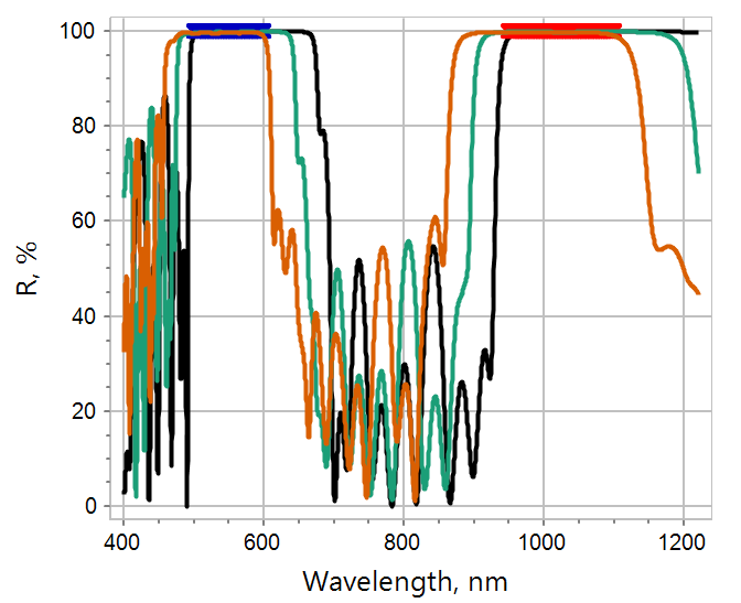
Dual-band high reflectors are multilayer coatings designed to provide high reflectance simultaneously at two separate, distinct wavelengths or spectral bands. Between and outside these two reflectance bands, the coating can have very different (often unimportant, or deliberately different) spectral behavior. Typical application: dual-wavelength laser systems (e.g., a fundamental laser line plus its second harmonic, such as 1064/532 nm or 1030/515 nm). This video showcases the design of a dual-band coating, optimized as a high reflector for both the fundamental laser wavelength of 1030 nm and its second harmonic at 515 nm, using OTF Studio thin-film software. The coating provides high reflectance within the wavelength ranges of 950-1100 nm (around 1030 nm) and 500-600 nm (around 515 nm), maintaining high reflectivity across the entire operating angular range of 0° to 45°.
Dichroic Beamsplitter
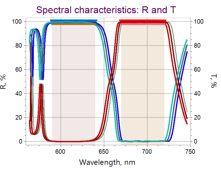
A dichroic beamsplitter is a multilayer coating designed to split an incoming beam by wavelength: one spectral region is reflected, and another is transmitted. This video shows how to design a dichroic beamsplitter operating at 45°±1° using the Multi-Start algorithm of OTF Studio. The multilayer must exhibit reflectance exceeding 98% in the range 590–640 nm and transmittance exceeding 98% in the range 670–710 nm. The video also explains a powerful and effective OTF Studio design algorithm that incorporates elements of machine learning - the Multi-Start algorithm - and uses the Smart Brush (cleaner) algorithm to remove thin layers while maintaining excellent optical performance.
Thin Film Immersed Polarizer
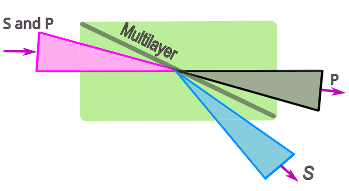
Optical coatings can be designed to separate light by its polarization state, transmitting one polarization while reflecting the other. Thin-film polarizers built this way are widely used, for example, in laser systems. This video shows how to design an immersed thin-film polarizer using OTF Studio software. "Immersed" (or "embedded") means the multilayer coating is sandwiched between two pieces of glass. A wide-angle polarizer is designed: the multilayer is immersed in a glass prism, and it must transmit P-polarization and reflect S-polarization for wavelengths 610-650 nm and incidence angles 50-70°. The video also demonstrates OTF Studio's Expressions feature - functions built from other spectral quantities, such as the ratio between s- and p-polarization reflectance.
Broadband Immersed Polarizing Beamsplitter
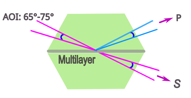
Thin film polarizing beamsplitters built this way are widely used, for example, in laser systems. This video shows how to design an immersed polarizing beamsplitter using OTF Studio software. "Immersed" (or "embedded") means the multilayer coating is sandwiched between two pieces of glass. A wide-angle, broadband polarizing beamsplitter is designed: the multilayer is immersed in a glass prism (refractive index 1.85), and it must reflect P-polarization and transmit S-polarization across the operating spectral range of 400-700 nm and incidence angles of 65-75°. The video also demonstrates OTF Studio's Expressions feature - functions built from other spectral quantities, such as the ratio between p- and s-polarization transmittance. In addition, it shows OTF Studio's angular plots.
📢 Disclaimer: Any short YouTube advertisements appearing alongside our videos are not uploaded by, endorsed by, or affiliated with OTF Studio Software. We are not responsible for this third-party promotional content.