Dispersive Mirrors in the Mid-Infrared Spectral Range
- Modern laser applications rely on broadband dispersive mirrors with high reflectance and a carefully tailored group‑delay shape. This shape controls the phase of ultrafast laser pulses. As a short pulse propagates through dispersive materials, it accumulates group delay. In mid‑infrared laser systems, pulses may travel through optical windows and crystals such as ZnSe, Ge, KBr, CaF2, ZGP, etc. These materials can introduce large dispersion, either individually or in combination. As a result, different spectral components of the pulse experience different delays. The pulse broadens, and its temporal shape may change. By introducing a dispersive mirror with an inverse group‑delay shape, the accumulated dispersion can be compensated, allowing the pulse to be compressed back toward its original shape and duration (Fig. 1).
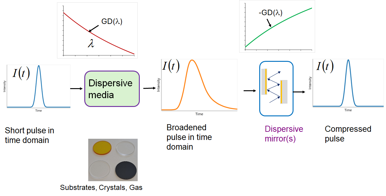
Fig. 1. Simplified scheme of pulse compensation.
- Typically, dispersive-mirror design challenges are defined by two main factors: bandwidth and the required group-delay shape. Group-delay variation is also a key parameter (Fig. 2).
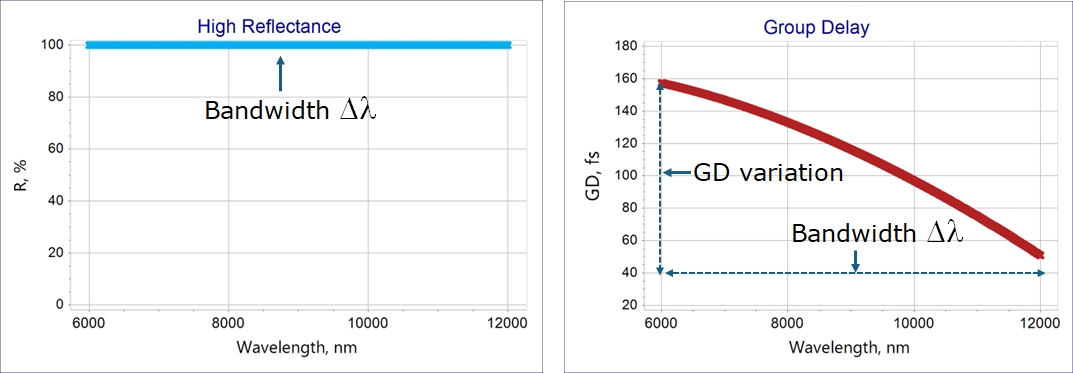
Fig. 2. Typical target specifications for dispersive mirrors in the mid-infrared spectral range: high reflectance (left) and GD (right).
- In dispersive‑mirror design, the spectral bandwidth is specified by the lower and upper wavelength limits \(\lambda_d\) and \(\lambda_u\). This bandwidth is commonly expressed in optical octaves:
\[ \Delta\lambda = \log_2(\lambda_u/ \lambda_d) \]
- In the example shown in Fig. 2, the 6-12 µm bandwidth corresponds to 1 optical octave, and the GD variation is 110 fs.
- In the visible and near‑infrared ranges, substrates and crystals such as fused silica, optical glasses, and Al₂O₃ usually exhibit a group delay that decreases with wavelength. In contrast, for most mid‑infrared windows and crystals, the group delay increases with wavelength. This difference affects the structure of dispersive mirrors. For visible and near‑infrared dispersive mirrors, a typical starting design is a chirped mirror with layer thicknesses that decrease with layer number (Fig. 3, left). For mid‑infrared dispersive mirrors, the layer thicknesses typically increase with layer number (Fig. 3, right).
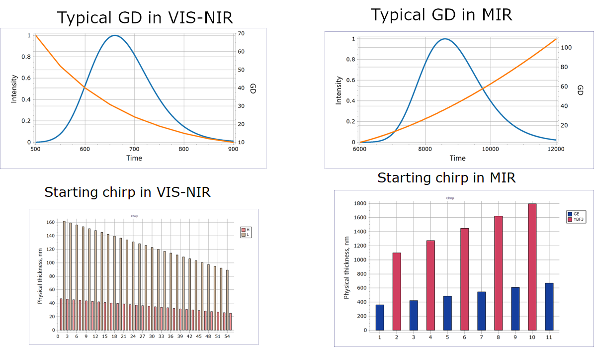
Fig. 3. Typical GD to be compensated and the corresponding dispersive‑mirror starting design for the visible–near‑infrared spectral range (left) and the mid‑infrared range (right).
- The powerful and extremely fast algorithms in OTF Studio enable designing mid-infrared dispersive mirrors with achievable GD variation within practically accessible bandwidth. For mid-infrared dispersive mirror design, the Needle Optimization and Gradual Evolution algorithms are typically used, and their Deep Search versions can be applied as well.
For mid-infrared dispersive mirror design, standard infrared coating materials can be used, such as Ge, YbF₃, ZnS, Y₂O₃, Si, and others. For broadband dispersive mirrors, material combinations with maximum refractive index contrast are generally preferable. Fig. 4 shows an example solution: a 16 layer Ge/YbF₃ dispersive mirror designed to compensate the group delay accumulated in a 1 mm ZnSe window.
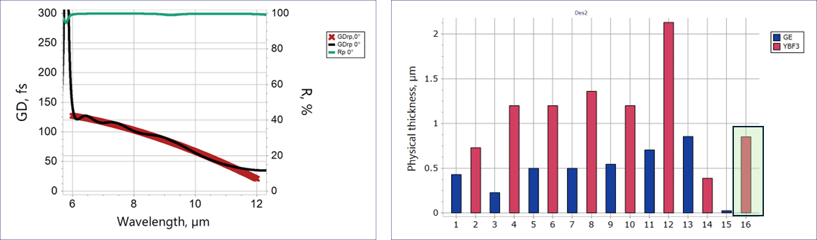
Fig. 4. A dispersive mirror design solution compensating GD accumulated in 1 mm ZnSe substrate.
- The target GD is not uniquely defined; only its shape matters, not its absolute value. A constant group‑delay shift does not influence pulse compression. Shifting the target GD by an arbitrary constant simply moves the pulse along the time axis without changing its shape. To relax the target requirements, a floating constant C can be introduced. OTF Studio provides a floating‑constants tool that allows the GD target to vary in absolute level while preserving the required GD shape (Fig. 5).
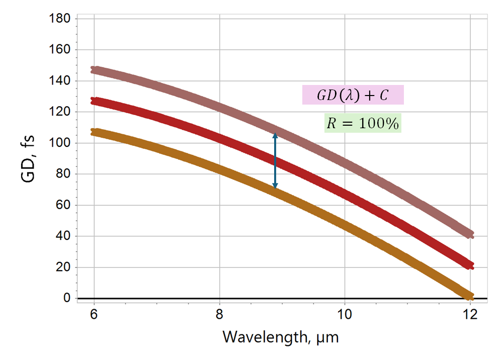
Fig. 5. Illustration of a GD target with a floating constant C.
- To improve environmental stability, it is sometimes necessary to add a capping layer on top of the design. However, even a thin capping layer can noticeably degrade the GD performance. Using the Refinement with Constraints algorithm in OTF Studio, the design can be re‑optimized with a capping layer whose thickness has a defined lower limit, preserving excellent spectral characteristics (Fig. 6).
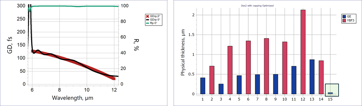
Fig. 6. Spectral performance of the dispersive mirror solution with a capping Ge layer.
- Ripples in group delay and group‑delay dispersion are inevitable due to physical reasons. In OTF Studio, you can model pulses in the spectral domain and compute how they appear in the time domain after interaction with the designed mirrors (Fig. 7). Fig. 7 demonstrates that the pulse performance remains unchanged even though a capping layer is added.
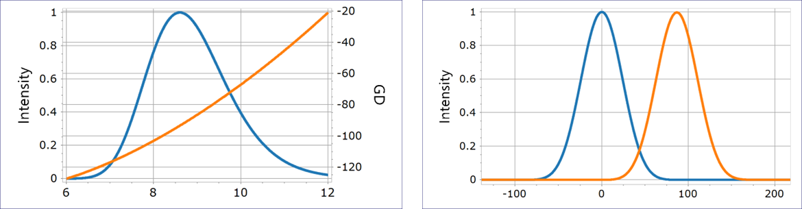
Fig. 7. A model pulse (bandwidth 6-12 µm) in the spectral domain (left) and the time domain (right).
- Typical layer thicknesses in the MIR range depend on the central wavelength of the spectral bandwidth and, naturally, on the refractive index of the materials. Very roughly, MIR layers are about ten times thicker than layers used in the VIS and NIR ranges. The estimations provided here allow you to predict average layer‑thickness values for each material. Another important design parameter in mid‑infrared coatings is the thickness of the thickest layer.
- Typical mid‑infrared broadband ranges exceed 0.6 optical octaves. The required GD variations can range from a few femtoseconds up to 1000 fs or more. In modern laser applications, the dispersive‑mirror specifications - bandwidth and GD variation - can be at the cutting edge of achievability, and not all parameter combinations are achievable. Our estimations help you assess whether your dispersive‑mirror specifications are realistically achievable and predict the expected total design thickness, the average layer thickness per material, and the thickness of the thickest layer.
- In the example considered above, the predicted values are:
– total thickness: 12–13 µm
– average thickness of Ge layers: 0.5 µm
– average thickness of YbF₃ layers: 1.2–1.3 µm
– thickness of the thickest YbF₃ layer: about 2 µm
- In practice, dispersive mirrors must be designed not for a single MIR substrate, but for a sequence of different windows and crystals used in a laser system. When a pulse propagates through thick windows or an assembly of windows, the group‑delay variation can become quite large, and the required bandwidth/GD‑variation combination may not be achievable with a single mirror. Fig. 8 illustrates the accumulated GD variation in ZnSe: approximately 110 fs for 1 mm and 220 fs for 2 mm.
- In many cases, this problem can be solved with a dispersive‑mirror compressor. It uses several dispersive mirrors and provides 2, 4, 6, or 8 pulse reflections. In this case, the total target group delay is divided by the number of reflections: 2, 4, 6, or 8. The group delay and reflectance of a pulse compressor with N reflections can be calculated as follows. The group delay is added for each reflection, while the reflectance is multiplied at each reflection. Of course, as the number of reflections N increases, the pulse loses some energy at each reflection.
\[ GD_\Sigma (\lambda) = N\cdot GD(\lambda), \;\; R_\Sigma (\lambda) = R^N (\lambda) \]
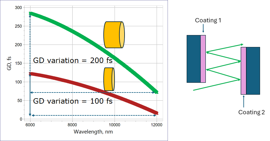
Fig. 8. GD variations accumulated in 1 mm and 2 mm ZnSe windows (left); simplified representation of a dispersive‑mirror compressor (right).
- OTF Studio provides a pulse analysis tool that allows you to model the interaction of an ultrashort pulse with the designed dispersive mirrors and estimate the expected level of intensity losses. For example, compensating the group‑delay accumulated in 2 mm ZnSe using the dispersive‑mirror design shown in Fig. 6 results in losses of less than 1 %.
- Due to the large thicknesses involved, mechanical stresses can deform optical components or even cause delamination and peeling of the coatings. Using OTF Studio, you can design multilayers while accounting for total coating‑thickness constraints and individual material‑thickness limits. You can also minimize the stress or compensate residual stresses on the backside. OTF Studio provides tools to insert barrier layers, capping layers, and adhesion layers while maintaining excellent spectral performance. In addition, you can design back‑side coatings (for example, antireflection coatings) that compensate the stress induced by the front‑side coating.
 Learn more in our YouTube video