AR coatings
  HR coatings
  Stresses
  Mid-infrared dispersive mirrors
Inline Reoptimization
Deposition errors are inevitable and can occur due to various factors, including:
- Instability in deposition rates
- Noise, offsets, scaling, and distortions in inline measurement data
- Instability in shutter delays
- Inaccuracies in optical constant values
- Inaccurate calibration etc.
These errors result in deviations between the experimental spectral performance and the expected theoretical performance.
With an increasing number of deposited layers and the accumulation of errors caused by measurement inaccuracies and calibration drifts, the measured spectral curves can significantly differ from the expected theoretical performance. Therefore, it becomes more logical to perform inline characterization after the deposition of each layer. This involves utilizing the recorded measurement data to determine the actual layer thicknesses and substituting them to the relevant calculations.
Even applying inline characterization, in certain situations, it may no longer be possible to achieve the desired theoretical performance. In the worst-case scenario, the deposition process may even fail. In such cases, reoptimization of the remaining layers, i.e., the layers that have not been deposited yet, can be carried out to mitigate the impact of the accumulated errors.
taReo offers reoptimization algorithms and tools that are known for their exceptional speed and efficiency. They possess the remarkable ability to perform design reoptimization without the need to interrupt the deposition process. You can find a visual representation of how taReo is implemented into the deposition process in Fig. 1.
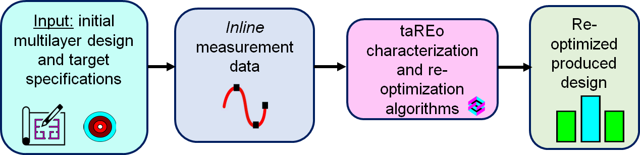
Fig. 1. Implementation of taReo reoptimization algorithms: prediction of the termination point based on the analysis of measurement inline data.
Example in Fig. 2 illustrates such a situation: even in the case of deposition errors, it was possible to achieve the excellent spectral performance.
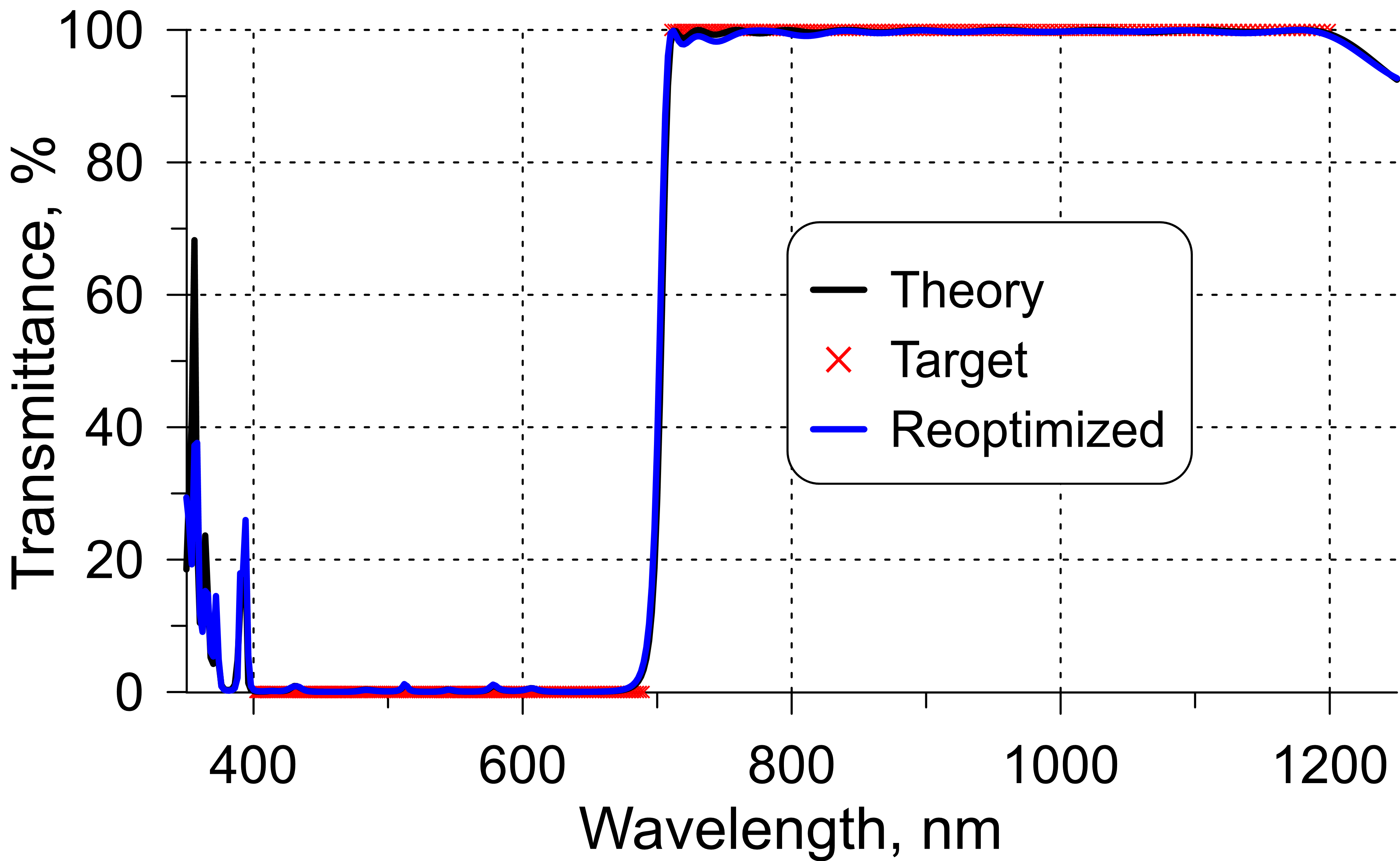
Fig. 2. Results of inline reoptimization: desired target performance (red crosses) was achieved despite of deposition errors. The performance of the reoptimized design (blue curve) is very close to the theoretical curve.
Example. Let's consider the deposition of a 44-layer cold mirror, following the design structure illustrated in Figure 2. Notably, the structure does not include any extremely thin layers.
After deposition of 30 layers, the correspondence between the experimental and theoretical data (Fig. 3) is getting worse. At this point, it is reasonable to perform reoptimization of the rest 12 layers (Fig. 4).
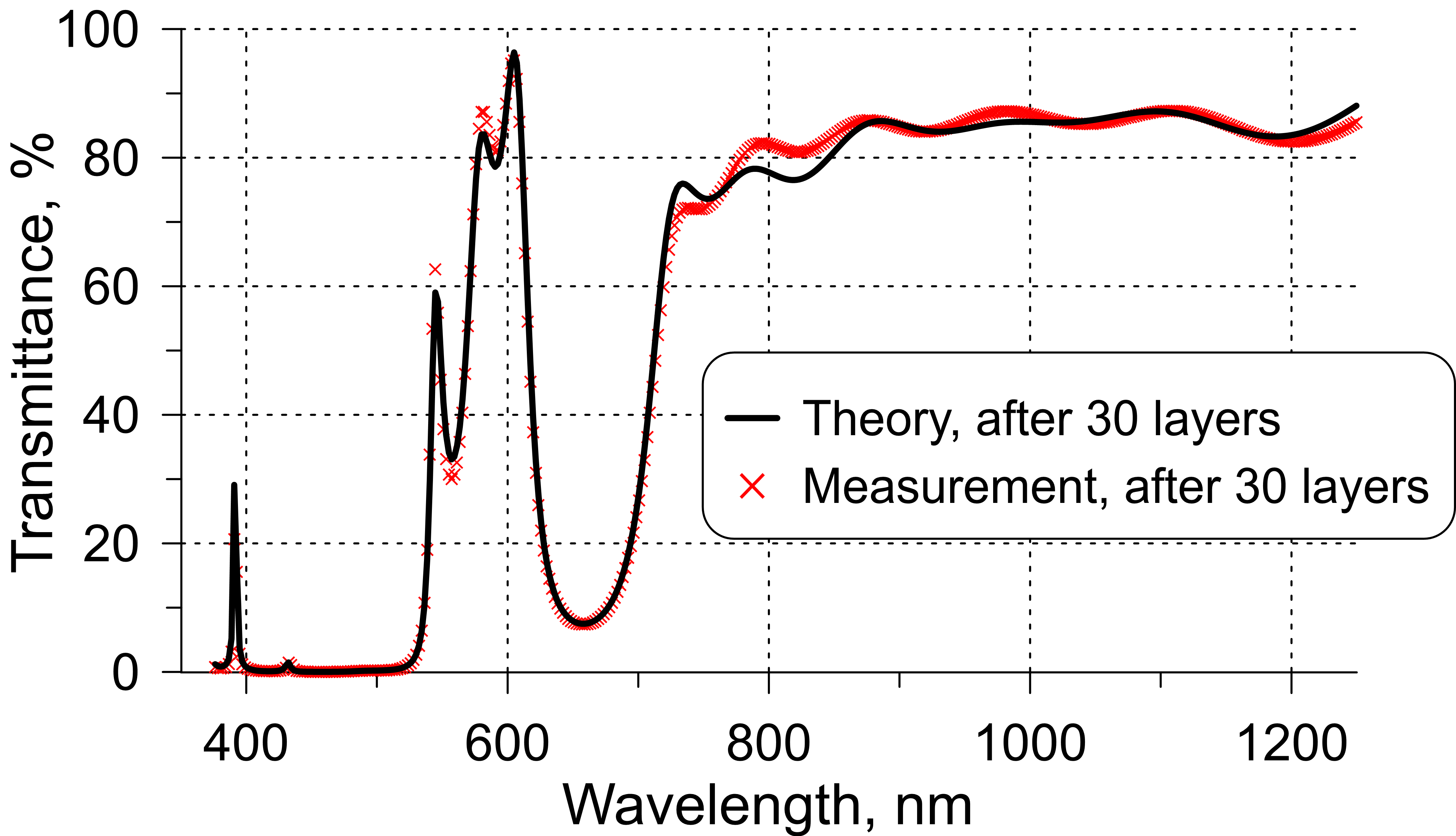
Fig. 3. Comparison of experimental inline transmittance recorded after the deposition of 30th layer (red crosses) and expected theoretical transmittance (black curve).
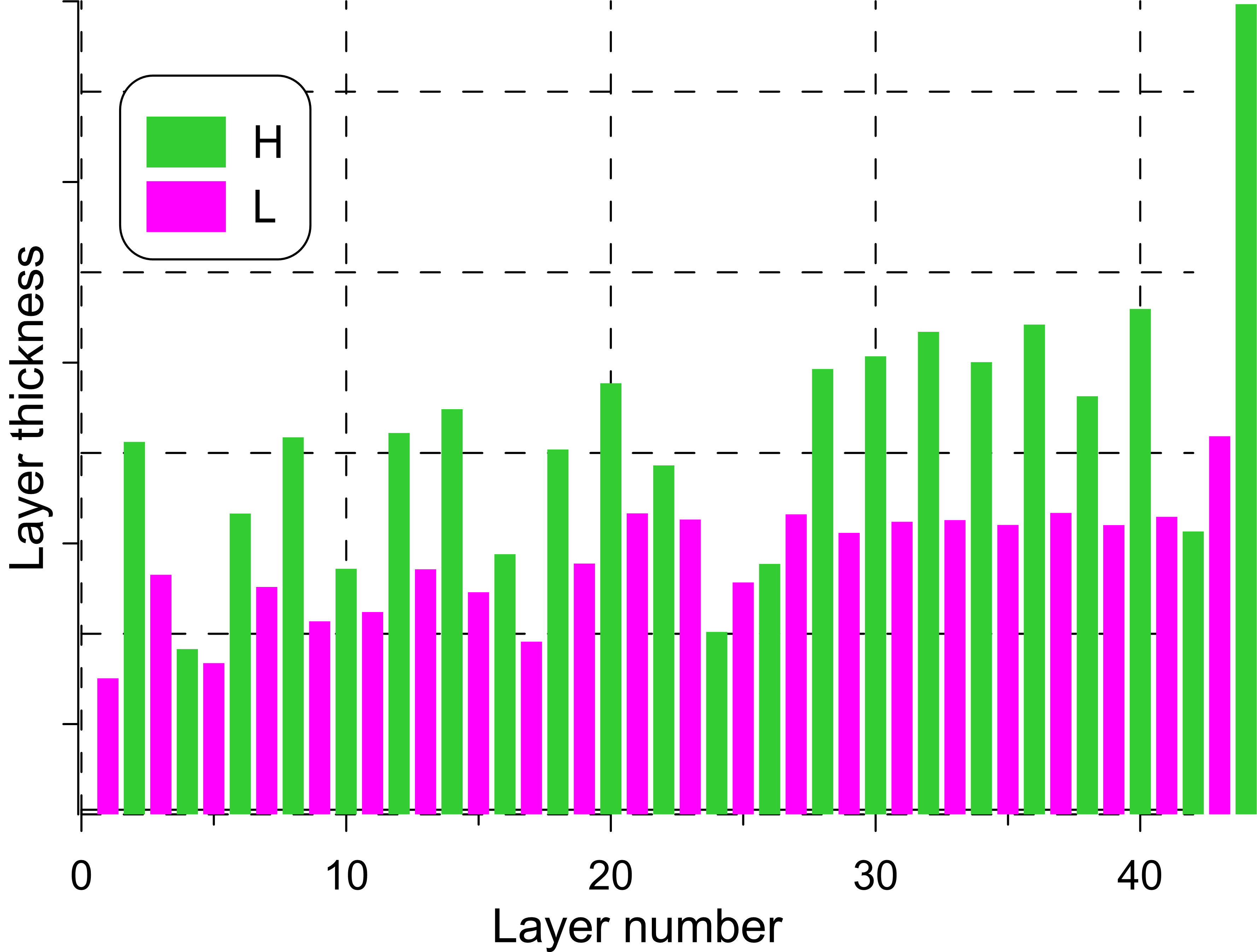
The remaining 12 active layers are shown in Fig. 4 by magenta and green bars. The first deposited 30 layers shown by black and grey bars are already fixed.
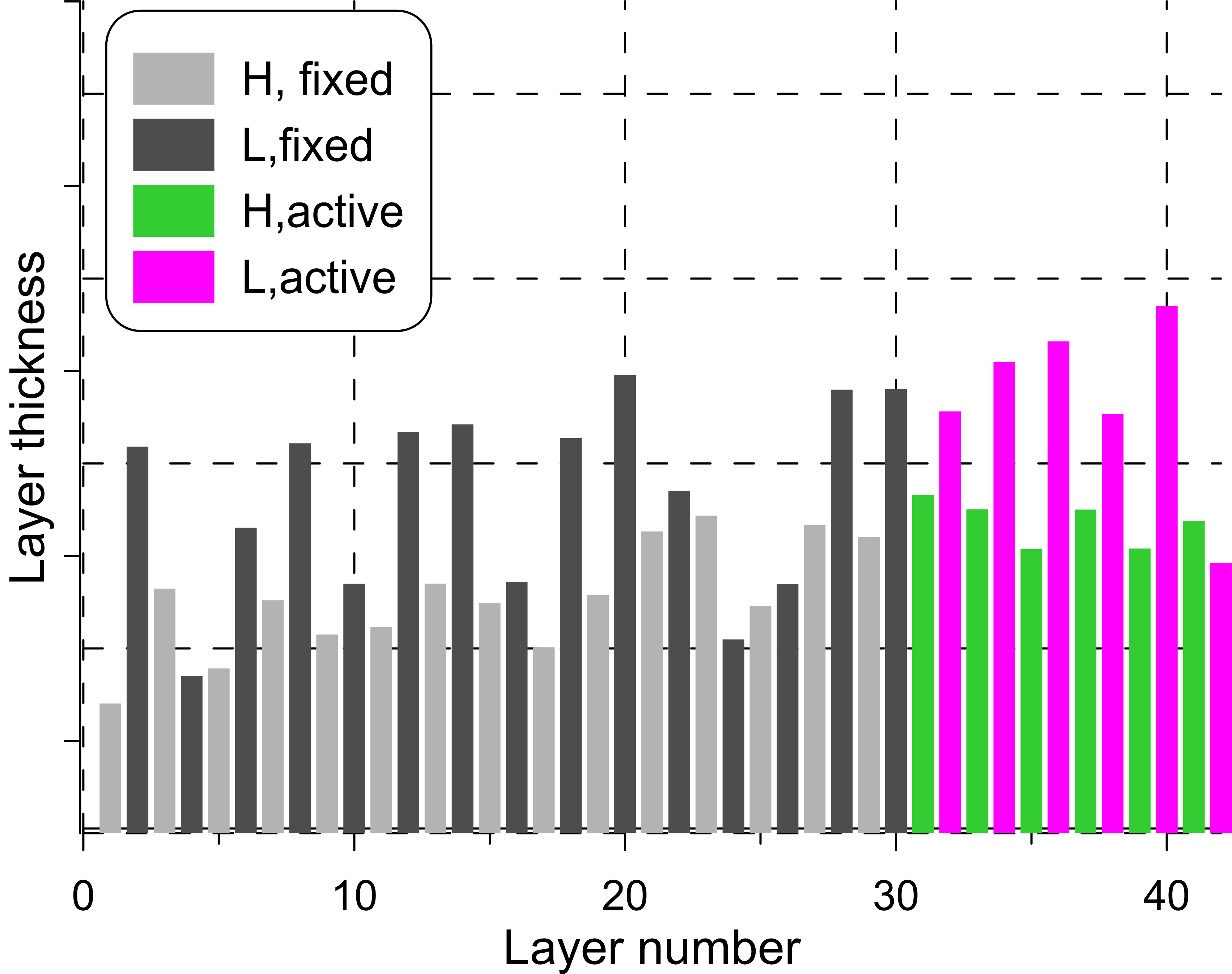
Fig. 4. Design structure after deposition of 30 layers and before reoptimization.
Reoptimization of the design with respect to the last 12 layers leads to the very nice correspondence between experimental and theoretical data (Fig. 2).