AR coatings
  HR coatings
  Stresses
  Mid-infrared dispersive mirrors
High reflectors
High reflective (HR) optical coatings, which maximize the reflectance of an optical surface in a spectral range of interest. The values of spectral characteristics outside of the specified HR region is typical of no interest. The most important characteristics of HR coatings are the width of the HR zone, peak reflectance $R_0$, and average reflectance over the HR range.
Metallic mirrors, which are thin films of silver, gold, aluminum provide high reflectance over broad spectral ranges. The surface of metal coatings is mainly very sensitive to environment impact. Also, metal mirrors are sensitive to cleaning. Typically, protective layers are required to increase durability and stability of HRs. Also, combinations of dielectric layers can be deposited on metal layers to enhance reflectance in specified spectral ranges.
Dielectric HR multilayers are good alternative to metal mirrors but their operating spectral ranges are much narrower. Here we tell about different types of HR coatings, their designing, and show some examples.
Quarter-wave mirrors
A multilayer consisting of alternating high- (H) and low (L)-index layers having an optical thickness of a quarter-wave is termed as a quarter-wave mirror (QWM) or a quarter-wave stack. Also, these mirrors are termed as Bragg reflectors or 1D photonic crystals.
If $\lambda_0$ is the central wavelength of a QWM and layer materials have refractive indices $n_H$ and $n_L$, then thicknesses of all layers are equal to $\lambda_0/4$. Layer thicknesses of H-layers are $\lambda_0/(4n_H)$ and layer thicknesses of L-layers are $\lambda_0/(4n_L)$. The width of the HR zone is dependent on the ratio of high- and low-refractive indices only. The peak reflectance $R_0$ is dependent not only on $n_H, n_L$ but also on the substrate refractive index $n_s$, the number of layers $m$, and on the QWM structure. There are four possible QWM structures:
- HLHL...HL (even number of layer, the last layer is L);
- HLHL...HLH (odd number of layers, the last layer is H);
- LHLH...LH (even number of layers, the last layer is H, and
- LHLH...LHL (odd number of layers, the last layer is L).
If you would like to calculate the width of the HR zone of a QWM as well as to estimate its peak reflectance $R_0$ depending on optical constants, the structures, and the incidence angle AOI, please try our QWM calculator.
As an example, reflectance of a 21-layer QWM at normal incidence (AOI=0°) is shown by the black curve in Fig. 1. The HR zone is centered around the central wavelength of 800 nm.
In the case of oblique incidence, the thickness of the QWM layers, $d_H$ and $d_L$ should be recalculated taking into account the effective refractive indices of layer materials:
$$ d_H=\lambda_0/\left(4\cdot \sqrt{n_H^2-n_a^2\cdot \sin^2(\theta)}\right), \qquad d_L=\lambda_0/\left(4\cdot \sqrt{n_L^2-n_a^2\cdot \sin^2(\theta)}\right),$$
where $n_a$ is refractive index of the incidence medium; $\theta$ is the AOI.
- In the case of oblique incidence, the HR zone will be centered around the same central wavelength $\lambda_0$. The width of the HR zone will be different (see example in Fig. 1). The HR zone in the case of s-polarization is broader than in the case of normal incidence (please try our QWM calculator); the HR zone in the case of p-polarization is narrower than in the case of normal incidence.
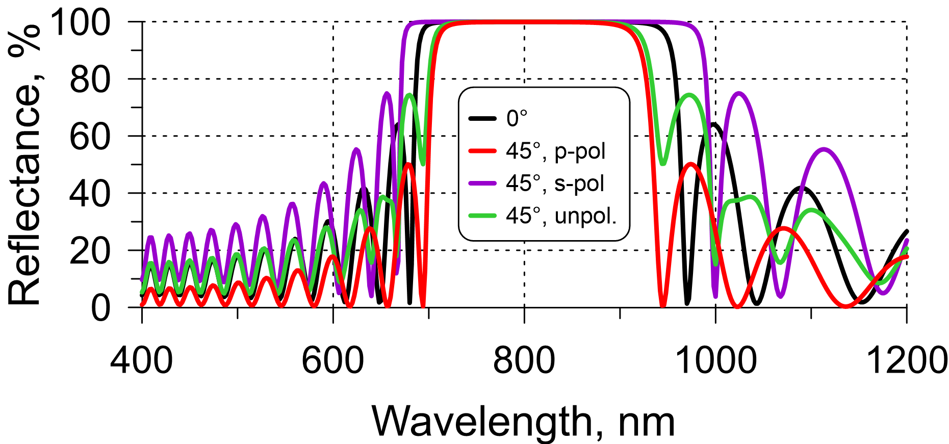
Fig. 1. Example: reflectance of a 21-layer QWM designed for the normal incidence and of a 21-layer QWM designed for AOI=45° (layer materials are the same).
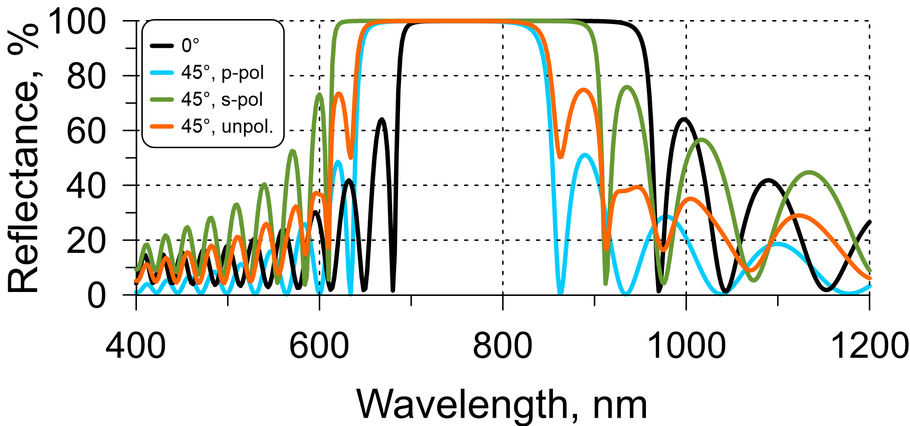
Fig. 2. Example: reflectance of a 21-layer QWM at the normal incidence, at AOI=45° in the case of s-, p-polarization, and unpolarized light.
- If a QWM was designed for a central wavelength $\lambda_0$, then if the AOI increases, the spectral characteristics shift to the shorter wavelengths (Fig. 2). The QWM at an AOI is not an QWM since the layer thicknesses are not quarter-wave any more. At a small AOI, the pattern of spectral characteristics is very similar to the performance of a QWM. With increasing the AOI, this behavior differs from the QWM significantly.
- The shifted QWM is centered at a wavelength $\lambda_{AOI}$ that can be approximately estimated as:
$$ \lambda_{AOI}=\frac{\sqrt{n_H^2-n_a^2\cdot \sin^2(\theta)}\cdot n_L+\sqrt{n_L^2-n_a^2\cdot \sin^2(\theta)}\cdot n_H}{2n_L n_H}\cdot\lambda_0 $$
- The width of the HR zone of a shifted QWM can be very roughly estimated using the same formula as for the normal incidence (please try here).
- It is important that the HR zone of the shifted QWM in the s-polarization case will be centered around the same central wavelength as in the p-polarization case.
- Along with the main HR zone centered around $\lambda_0$, the QWM reflectance exhibits additional HR zones centered around $\lambda_0/3$, $\lambda_0/5$, .... (see example in Fig. 3). The main HR zone is centered around 1200 nm; the second one - around 400 nm; the third one - around 240 nm. The additional HR zones are much narrower than the main HR zone. The widths of these HR zones can be calculated here.
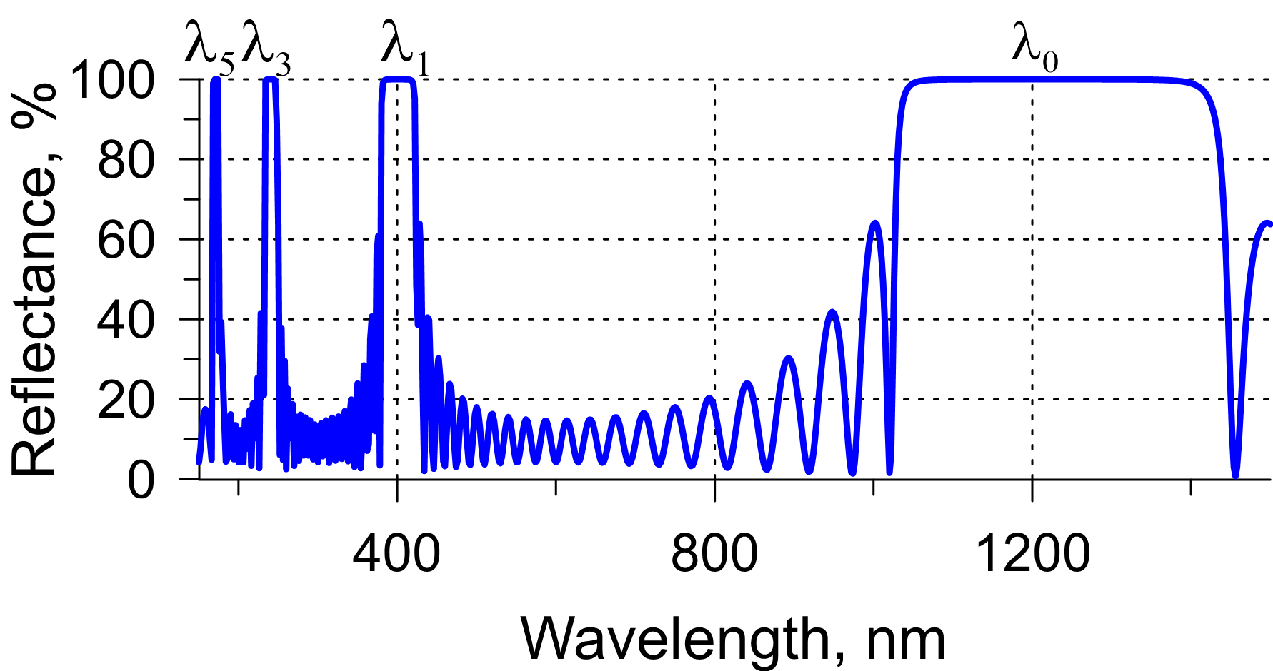 Fig. 3. Reflectance of a 21-layer QWM at the normal incidence in the range 150-1500 nm: the main and two additional HR zones are demonstrated.
Practically, the additional HR zones can be used in the design process of quasi-notch filters or band-pass filters with a narrow HR zones. For example, a QWM centered at 1500 nm exhibits a narrow HR zone around the wavelength of 500 nm; it means it can be used as a starting point to design a filter with a HR zone of about 50 nm bandwidth.
Chirped mirrors
- It is seen that the HR zone of QWM is relative narrow. For dielectric mirrors consisting of typical VIS-NIR thin-film materials, the bandwidth is about 0.35-0.45 optical octave or in other terms $\pm 15\%$ of $\lambda_0$. In the mid-infrared case, with such combinations as Ge/YbF3 thin-film materials, the bandwidth is about 0.9 optical octave or $\pm 30\%$ of $\lambda_0$. A well-know combination Ge/ZnS provides the HR bandwidth of about 0.6 optical octave or $\pm 20\%$ of $\lambda_0$.
- You may need to design and produce a really broadband HR coating with the bandwidth of more than one optical octave. There are different approaches to design such HR coatings. One of the them is based on the optimization of a so called chirped mirror or in other terms a smeared mirror (Fig. 4). The design structure can be obtained from the QWM structure by a linear variation of layer thicknesses (see an example in Fig. 4, right panel).
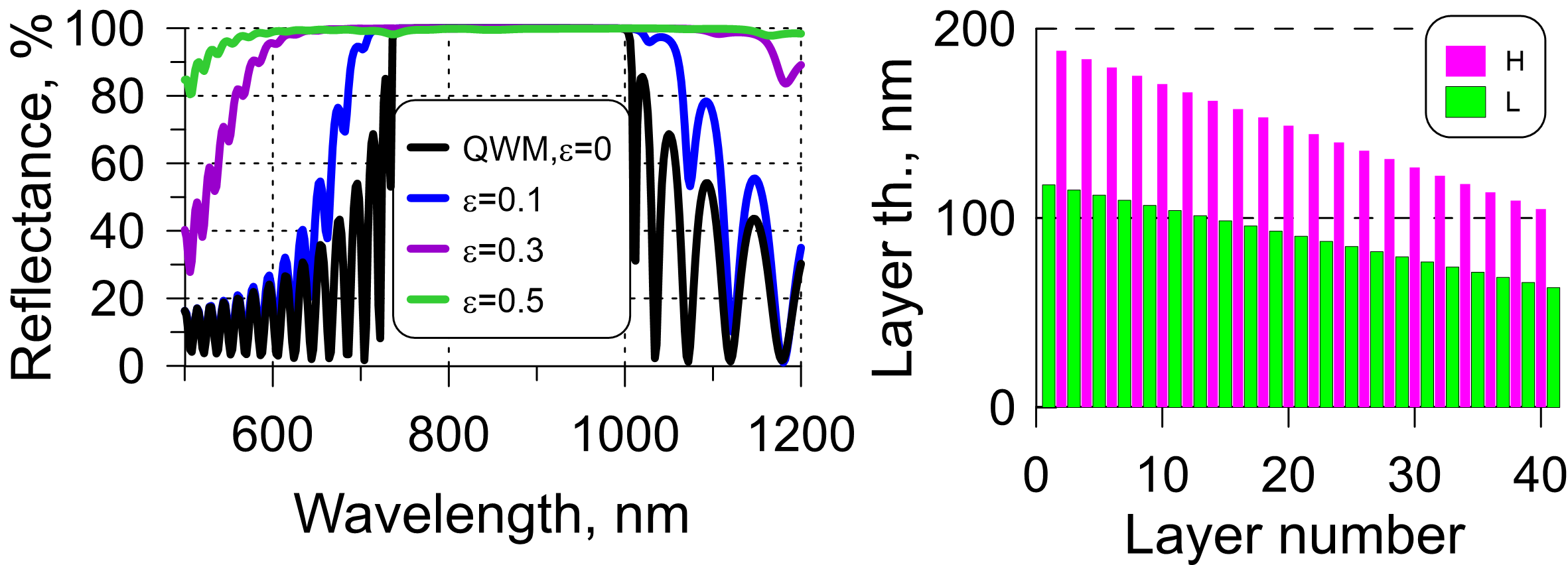
Fig. 4. Left panel: reflectance of chirped mirrors calculated for three different $\epsilon$ values. The value $\epsilon=0$ corresponds to the quarter-wave mirror; right panel: structure of a 41-layer chirped mirror corresponding to $\epsilon=0.3$.
- The layer thicknesses can be specified using a chirped parameter $\epsilon$ characterizing increasing or decreasing layer thicknesses. Typically, layer thicknesses are decreasing as shown in Fig. 4. However, there are situations when the thicknesses are increasing. Such design problems exist in the field of dispersive mirrors operating in the mid-infrared spectral ranges.
- Examples of chirped mirror performances with different $\epsilon$ values are shown in Fig. 4. Broader HR bandwidth correspond to larger $\epsilon$ values. The peak reflectance as well as average reflectance in the HR range is a little bit lower than in the case of QWM.
- It does not mean, of course, that increasing $\epsilon$, broader and broader HR coatings can be obtained. If the chirped parameter $\epsilon$ grows, more and more reflectance dips appear close to the boundaries of the HR zone. The maximum reasonable $\epsilon$ values are between -0.6 and +0.6.
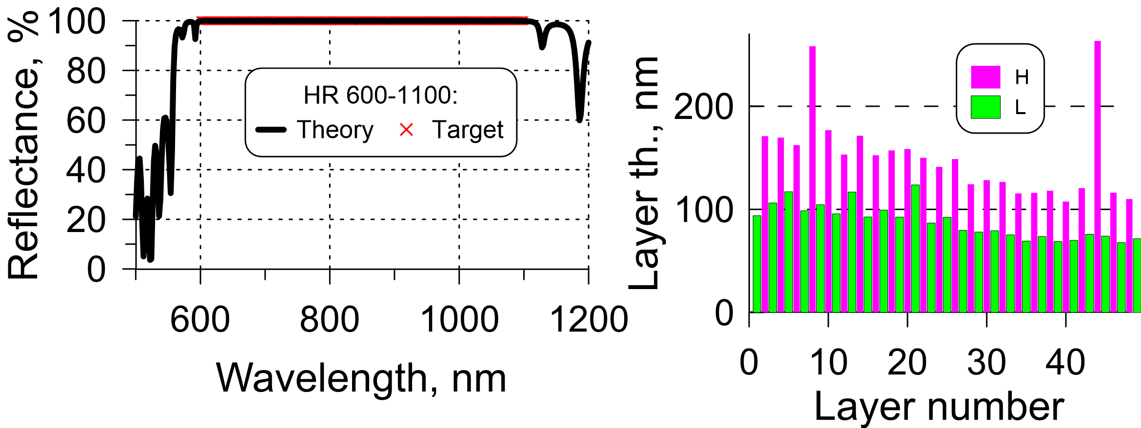
Fig. 5. Left panel: reflectance of a 48-layer HR design obtained from a chirped mirror with $\epsilon=0.3$ and $\lambda_0=850$ nm; Right panel: structure of the 48-layer high reflector for the spectral range 600-1100 nm.
- Chirped mirrors can be used as good starting designs of HR design problems. In Fig. 5, a HR coating operating in the range 600-1100 nm is shown. The design exhibits very high reflectance in the HR zone. As a starting design, a chirped mirror with an appropriate chirp parameter $\epsilon$ was used. The final design structure (right panel, Fig. 5) resembles the starting design (chirped mirror).
- If you have your specified HR spectral range and optical constants, you can find the reasonable chirp parameter $\epsilon$ using our chirp calculator. Also, here you can estimate required thicknesses of coating layers.
- For the example in Fig. 5: the central wavelength $\lambda_0=850$ nm, layer materials have refractive indices 2.35 and 1.45. The required HR bandwidth is 500 nm. With $\epsilon=0.3$, it is possible to cove the HR zone of 500 nm width.
Ultra-broadband high reflectors
If the specified HR range is larger than one optical octave, the HR coating is ultra-broadband. In Fig. 6, reflectance of an ultra-broadband HR covering two-octave HR spectral range is plotted: in the scale 0-100% (left panel) and in more detail in the scale 98-100% (right panel).
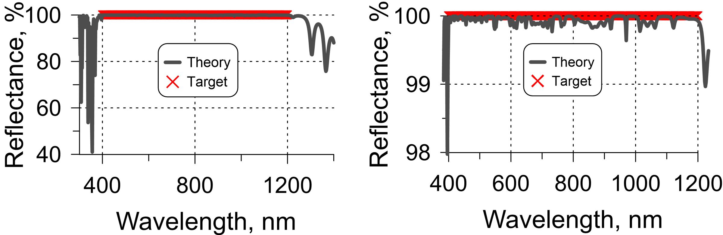
Fig. 6. Reflectance of a 96-layer HR design with the HR zone covering two optical octaves from 400 nm to 1200 nm (reflectance is plotted in two scales).
A typical problem in the course of the HR synthesis is ultra-narrow reflectance dips caused by resonances in the design structures. In order to avoid such dips, special design tricks are required.
One of the approaches to HR designs is using a combination of several querter-wave mirrors centered at different central wavelengths inside the HR operating range. This approach allows you to obtain quasi-quarter-wave stacks with no thin layers. One of the examples of such stacks is demonstrated in Fig. 7 (right panel). A 84-layer HR design exhibits high reflectance over the two-octave spectral range from 400 nm to 1200 nm (Fig. 7, left panel).
In order to find such a combination, we need to estimate how many stacks may be required. Assuming that layer materials have refractive indices 2.35 and 1.45, we can estimate width of HR zone of a QWM that is about 0.5 optical octave. Then, to cover the two-octave HR range, we need four QWMs. Estimations of the boundaries of the QWM HR zones allows you to suggest that the center wavelengths of the QWMs will be around 440 nm, 600 nm, 800 nm, and 1050 nm. Of course, you need matching layers between the QWM stacks. As you see in Fig. 7, the HR design consists of four quasi-quarter-wave stacks and matching layers.
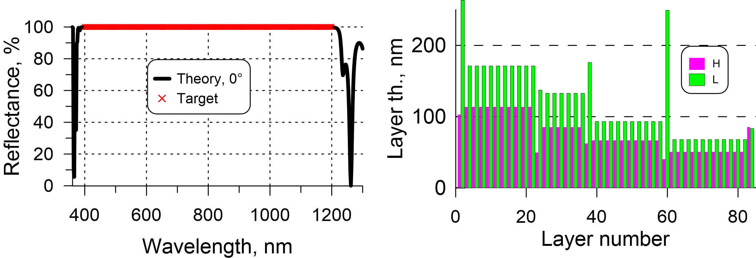
Fig. 7. Reflectance of a 84-layer quasi-quarter-wave HR multilayer with the HR zone covering two optical octaves from 400 nm to 1200 nm (left) and the design structure (right).
Multiple-band high reflectors
There are other types of HR coatings, for example, high reflectors operating in two HR zones (dual-band HR multilayers) or in three HR zones (triple-band multilayers). Also, HR coatings can operate at oblique incidence and in an specified angular range. In Fig. 8 (left panel), reflectance of an HR coating operating in two spectral ranges 500-600 nm and 950-1100 nm centered around two laser wavelengths of 532 nm and 1030 nm, respectively. The HR coatings operates in the angular range from 0 to 45°. A design solution is shown in Fig. 8 (right panel). The HR multilayer is a superposition of two quasi-quarter-wave multilayers and matching layers.
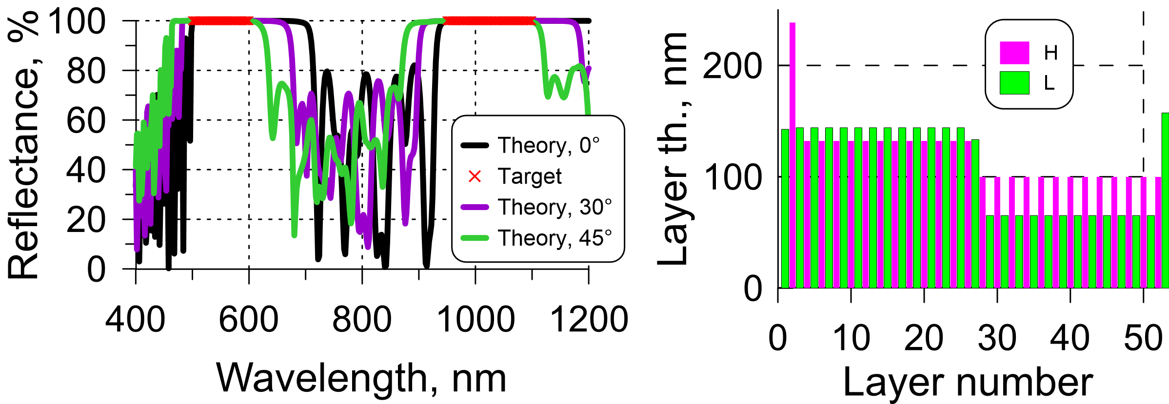 Fig. 8. Reflectance of the 52-layer high reflector and its quasi-quarter-wave design structure.
In practice, the HR requirement can be specified not only for spectral characteristics but may contain other demands, for example, high laser damage threshold or low stress. Dispersive mirrors require additional specifications on the phase properties.
References:
H.A. Macleod, Thin-Film Optical Filters, 4th ed. (Taylor & Francis, 2010).
P.W. Baumeister, Optical Coating Technology, SPIE Press, 2004.